![]()
 Welcome to K5KTF
![]()
For information on our in-person testing, visit this Link For the Decker Challenge info, click HERE Here is a print of the HRD Mapper of my contacts (all modes, all bands) as of 8-3-2010-2010 Here is my QSL cards so far, either downloaded from eQSL.cc or scanned in directs. Here is my SSTV page , which has all the slow-scan TV I have received over time (latest ones first) Instructions on making the USB extension cable going up to the Webcam can be found here
Here is a print of the HRD Mapper of my contacts (20 meters) as of 8-3-2010
If you see your state or country not worked yet, and would like to sked, email me Jim@k5ktf.com and we can arrange something.
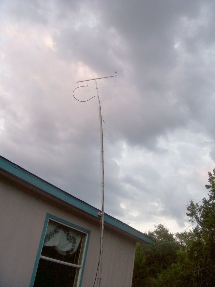
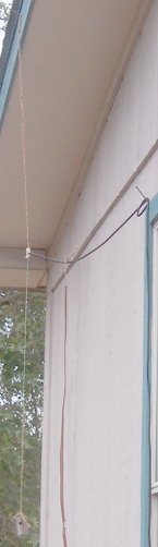
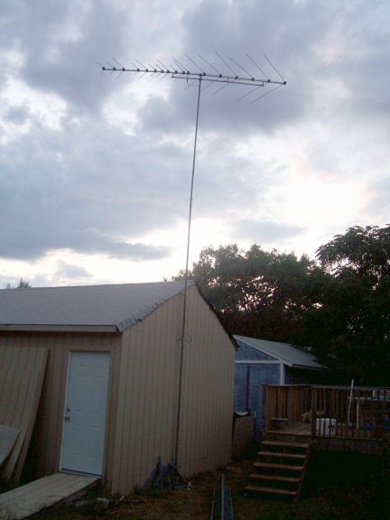
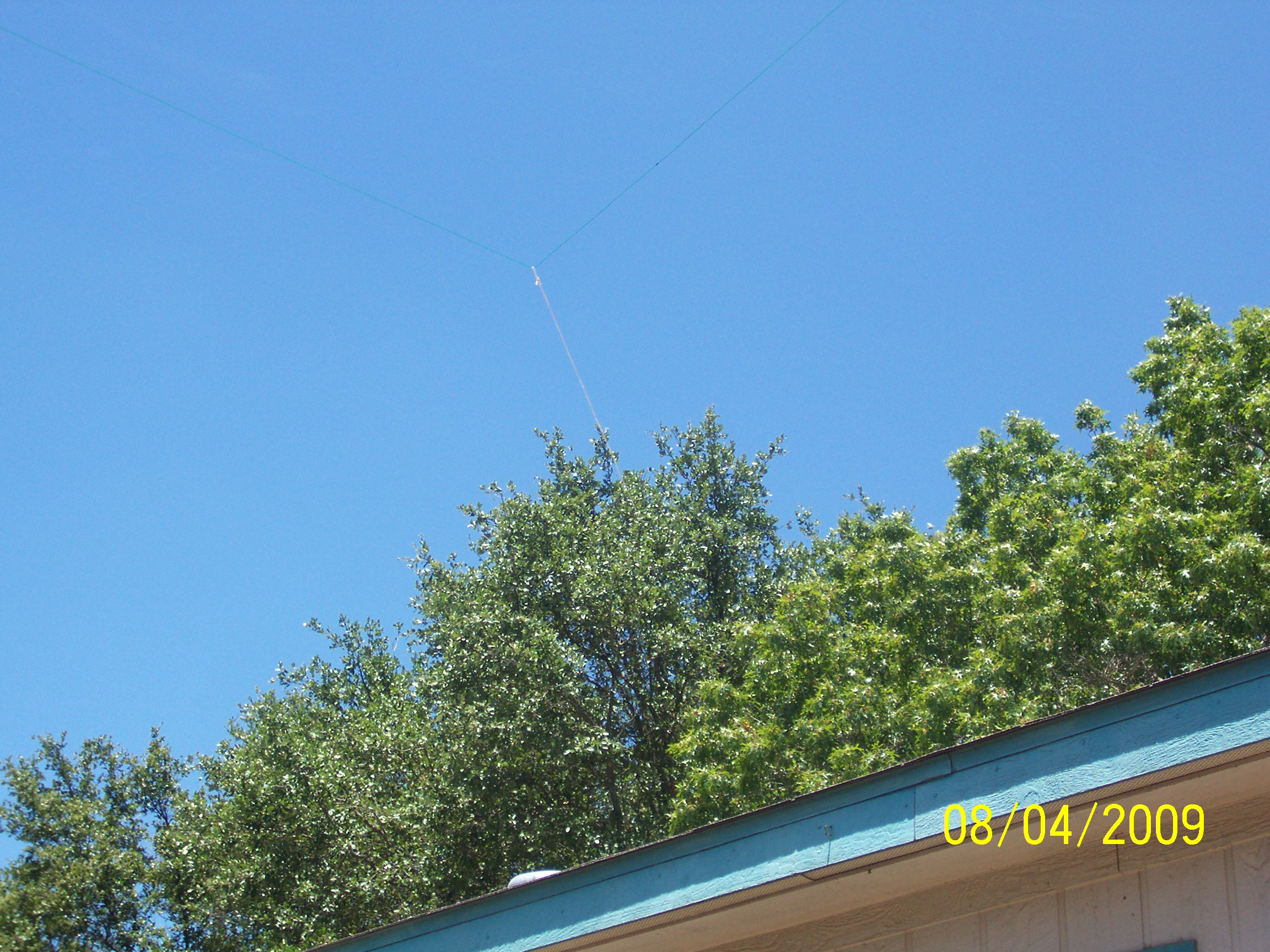
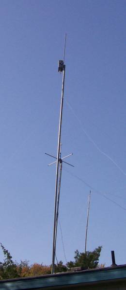
Notice the cam on the upper right of the antenna:
That is what is giving you the live picture at the top of this page.
www.hamuniverse.com/hentenna.html and WA0ITP's Page
K5KTF is Jim's HAM (amateur radio) callsign.
I passed the Technician exam back in June of 2008, A'cing (100%) the first try!
I then bid on and won a Yaesu FT-208 2 meter handy-talkie (HT) with a drop in charger/power supply.
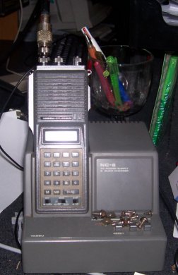
$20 including shipping from the previous owner in Florida.
The radio was cheap because 1: It had a broken battery terminal (not a biggie to fix) and 2: it does not have CTCSS/PL tone encoding.
A tone board for this radio will run about $30, which will be coming in the near future.
This is what I currently use in the house most of the time.
I then proceeded to make my first 2M antenna.
Take an 18" piece of CAT5e network cable. Whack off any RJ-45's it may have.
Remove 2 of the pairs (I used the orange and green pairs) from the cable. KEEP EACH PAIR TWISTED.
Strip about 1/4" insulation off both sets of pairs about 2" from one end of each pair.
Strip off about 1/8" to 1/4" of insulation from the same end.
On each twisted pair, make a loop on this same end, so that the end meets back the 2" bare spot.
Solder nice clean joints here (no cold joints or sloppy soldering.....)
Now, once soldered and clean, stretch the loop out so that it becomes thin and you have a point at the halfway mark of the loop.
Measure from the tip of the loop and cut the other end at 17" for each twisted pair.Strip off 1/8" to 1/4"
Solder one pair to the center of some 50-ohm coax of your choice, and the other pair to the shield/ground (earth for you Brits :-) )
I did the orange to the center (signifying HOT), green to the shield (since green is usually ground in electrical stuff)
Tie a 6" piece of rope or twine (NO METAL HERE) to each loop. One twine tie a weight to (this COULD be metal, but avoid if possible)
Use the other twine use to hang from a nail in something high....
On mine, I got an SWR about 1.2/1.3. Tests to other stations showed not a bad output, considering I had it hanging about 15' to the top,
and only running 2.5 watts from the FT-208R HT.....
This antenna was decomissioned once I got the hentenna up and going.
Then at Summerfest down in Austin this year, I picked up a (Kenwood) Trio TR-7950 for $50, and once we got home and opened it up,
again, no tone board...(and another $30 :-| )
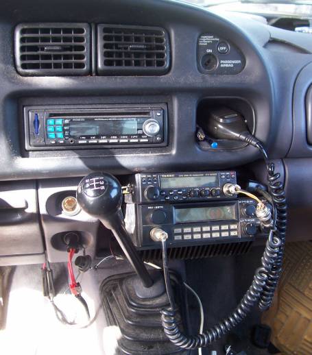
This is installed in the truck, hooked up to a NMO mount 2-meter antenna.
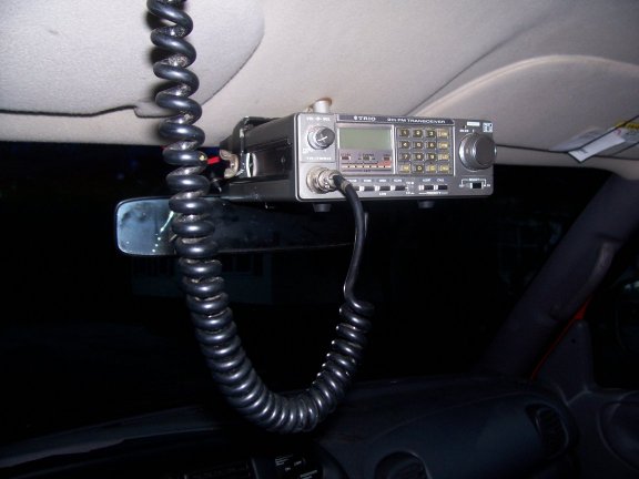
If that mounting bracket does not look stock, its because its not.
It didnt come with one, so being the resourceful person I am, I made that from a piece of angle iron (cut the angle off)
and bend to fit around the rig. Then cut 2 small squares, bend a small curve to allow the bolt-heads to slide past the radio,
a couple bolts and wingnuts and then mount to existing holes in the roof metal above the headliner
(looks like they are for when a console is to be mounted up there).
Still need to install some sort of hook to hang the mic from (right now it rides above the visor).
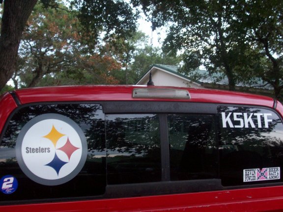
This required boring a hole in the roof and mounting the mount, solder on the coax inside the roof,
then screwing on the antenna base, and finally insert the vertical element.
Checked with a MFJ dual/crossing needle SWR meter, and it showed 1:1.2 at 147.000, so I just locked down the setscrew.
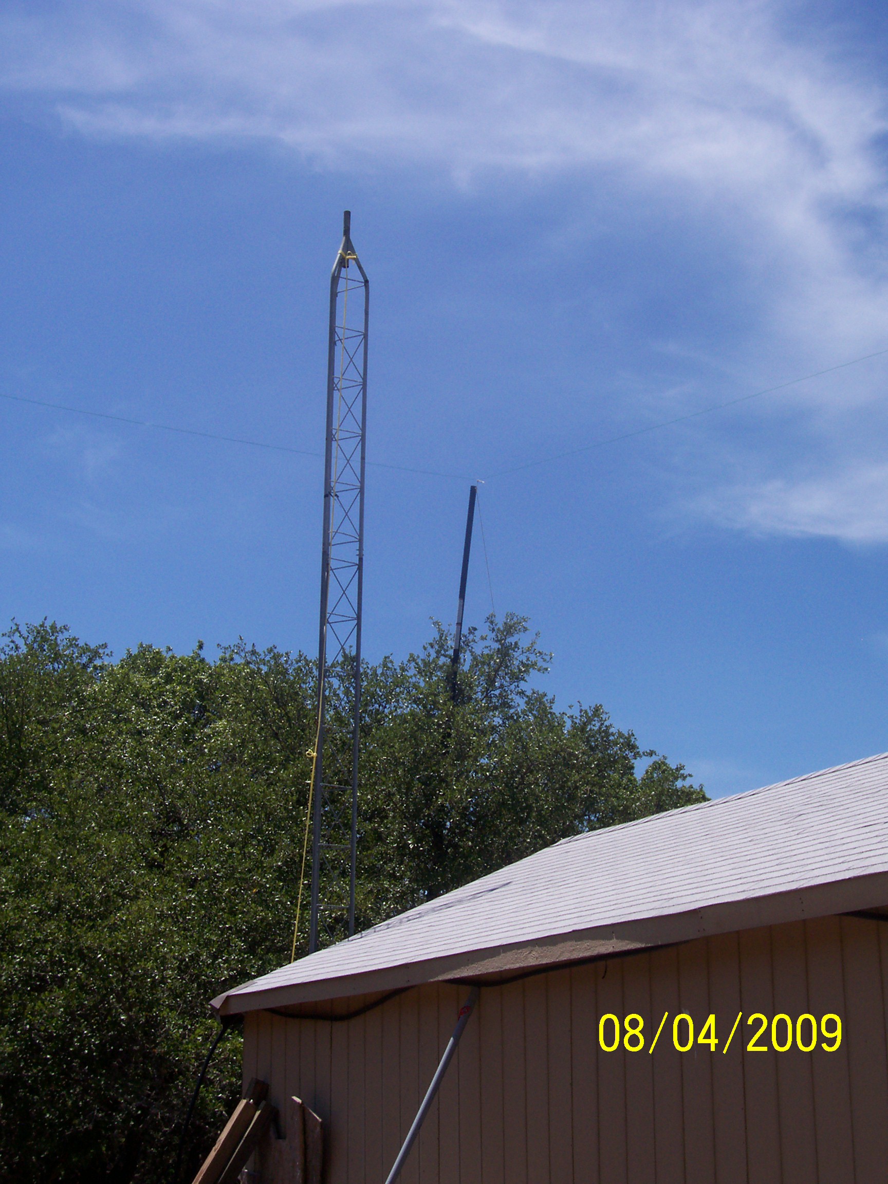
About the first week of September 2008, I got an email from KE5RS that he had some tower sections he was looking to offload.
It was 5 regular sections and one 'gooseneck' top.
I have a buddy Brian, AB5KT out in Thorndale who is also elevationally challenged, so we decided to share the sections.
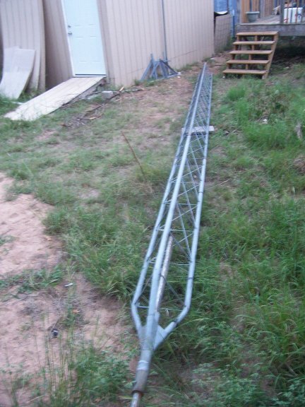
This is what I ended up with, about 30' worth, which is all I think I need right now, since the home QTH sits at about 1070'MSL.
It still needs bolted together and hoisted up. Havent decided whether it will go against the house or against the shed, where the TV mast/antenna is now
and will also be home to more of my creations (whatever antennas I build)
So then on September 6 2008, my 13 year-old son and I took a ride down to meet Joe W5HS and his group
at The Quarries sports complex. It was the first Saturday of the month!
Kyle KE5WHB passed his Tech exam, missing only 4 ! Woo Hooo Congrats ma boy!!!
I proceeded to pass my General Exam, missing 5.
We then took the next level each, him making 12/35 on General and I with a 24/50 score for Extra.
We were not bummed though, as we both acomplished what we came for.....
A future project will be taking the left-hand dish shown here (8' mesh),
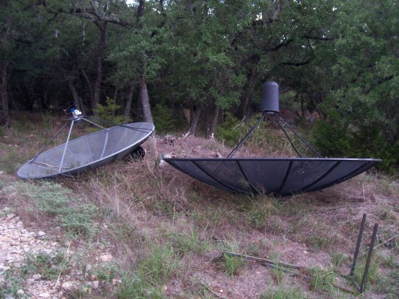
attaching the azimuth mover and finding something to work as an elevation mover (probably just mod'ing another AZ mover to work EL),
tying that to a dedicated computer that will be loaded with software to calculate bird (satellite) positions and track automatically, and control the movers
Then I will remove the TVRO feedhorn and LNB's, and creating feeds for 2M/70cm/etc (whatever I need to bounce the birds)
The right-hand dish (10') will be used for the main TVRO for the house until I get the 12' a guy I know will be decomissioning and letting me haul off ;-)
Then the 10' will be for the bedroom, and the 12' will be for the living room.
Each will have at least 1 4DTV receiver (C & Ku bands, both Analog and Digital).
Then I will try to acquire at least one nice FTA (free to air) receiver, so I can watch NASA TV again
(they moved from analog to FTA digital a few years ago).
But first I need to get 4" O.D. poles in the ground!
I am contemplating using 4" PVC pipe and filling with concrete to sturdy it up. Im thinking if I strap the pipe against the workshop eave,
it will be strong enough that I could have the dishes mounted above the workshop roof to get a better view of the Clarke Belt over the trees.
I had thought about getting roof-peak mounts, but if by chance a gust wants to make sails out of the dishes, I dont need the roof coming off :-)
UPDATE 10/15/2008: You can now see my feeble attempts at 2M SSTV reception HERE.
I have my R.S. Pro-50 scanner attached to the log-periodic TV antenna shown above (I know... its 75 ohm... blah blah),
and then a cable going from its headphone jack to my MIC input on the one sound card. Then I have MMSSTV running in AUTO mode,
then finally KE5RS's FTP Widget running to transfer any pictures over to the web site.
UPDATE 10/27/2008: My New 4 element 2-meter beam!
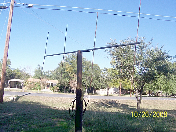
Built from dimensions found HERE, but as usual, made from scrap I had laying around.
I started by drilling a 1/4" diameter hole all the way through, as perpendicular as possible, about 1" from the end of 1/2" EMT electrical conduit.
Make sure the holes are snug fit for 1/4" diameter copper tubing, the kind they sell in a roll to hook water up to your refridgerator for ice/in-door water, etc.
Then 24-1/4" from the center of that hole, I drill another hole, this time 3/8" diameter. You will find out WHY the hole-size difference soon. ;-)
And then, from the FIRST hole, go 49" and drill another 1/4".
Finally, 71-1/2" from the FIRST hole, the last 1/4" hole.
Ok, so now we have 4 holes close to perpendicular through the pipe. Cut off the pipe about 1" past the last hole.
Time to cut some 1/4" soft copper tubing:
4 pieces, 1 each of 38-1/8", 36", 34-1/2", and 34-3/8" long.
The longest is your reflector, and goes into the first hole.
If you drilled it correct, the pipe should be real snug and you would have to work it through the EMT.
Get it exactly halfway through the conduit. Measure between the end of the copper and the edge of the EMT, to make sure you have the same amount on either side.
Once you have it exactly halfway, using a hammer and a nail/nailset/small screwdriver/etc, peen the EMT around the copper,
making small dents in the EMT steel that will kinda smush it into the coppper, holding the copper in place.
Do the same for the 3rd and 4th longest copper pieces. The antenna goes from longest to smallest in order down the beam.
But we will do the 2nd piece last, since it is the Driver element and will take the most work.
OK, now that you have the 3 non-driver elements in place and peened so as to not let them move, time for the driver.
Measure the 36" piece and mark it at 18" (halfway). Cut this element at that mark, so you have 2 18" pieces exactly.
Now, find you an old plastic venetian blind, that has broken and your about ready to throw away (or into your shop as "You never know when Ill need....", much to your wife's chagrin :-) )
You know that plastic rod you turn to tilt the shades open and closed? Good... Get it!
Cut off 2" of that rod. If your as lucky as I was, its ALMOST 1/4" hollow!
Take that 2" piece and drill down through to open the inside up to 1/4". (the first one I made, when I pressed the copper into it, it split, so DRILL IT!!)
Press that piece of plastic halfway through the 3/8" hole in the EMT tubing. (you may have to wallow it out with the drill to fit snug)
Then measure and press in each of those 18" copper pieces, but keeping the inside end about 1/4" from going inside the EMT.
Take a small drill, and drill 2 holes (one each side of the EMT) through the plastic and through the copper, about 3/4" from the EMT on each side.
Drive a sheetmetal screw through these holes, and attach your coax, center to one screw, shield to the other.
Insulate the shield with heatshrink/electrical tape/etc, so it doesnt touch the boom or other elements.
Hook it to your favorite Standing Wave Ratio meter (SWR will work too :-) ), and check it out on low power.
The picture above shows it stuck into a 'V' I cut into that piece of wood, and then stuck that into a TVRO dish mount I had.
My meter showed about 1.2 at 144.500, and 1.15 at 147.895, and not over 1.2 anywhere else in the band! No adjustment needed!
I have mine set vertical for now, as I was talking on repeaters here in Austin. Quite directional, as it should be!
If I pointed it east, away from Westlake TX, where the 146.94 repeater lives, I get 1 maybe S1 to S3 on the radio.
Spin it to the south/southwest though, and we get S9+20!!!
Normally, with the regular omni thats on the truck, I get S7/S9 from my home QTH.
I REALLY need to find me a field-strength meter of my own, so I can test my creations... muuuhahahahahaha
UPDATE 1-7-09:
Boy this page is really getting convoluted. I need to get this redone sometime (VERY) soon.....
Anyways......... If anyone is looking for pulled tubes, CLICK HERE.
I finally went through my stash and sorted/catalogued because a friend of mine was looking for a certain one.
To give you an idea of the last time I saw these tubes out of the box, they were wrapped in newspaper dated October 14, 1984.....
If you see something you need, jim@k5ktf.com or 512-563-9437
Also, last Saturday I made a visit to Dave KD5EPO and picked up Ishmael KB5AVB's old Yaesu FT-101F.
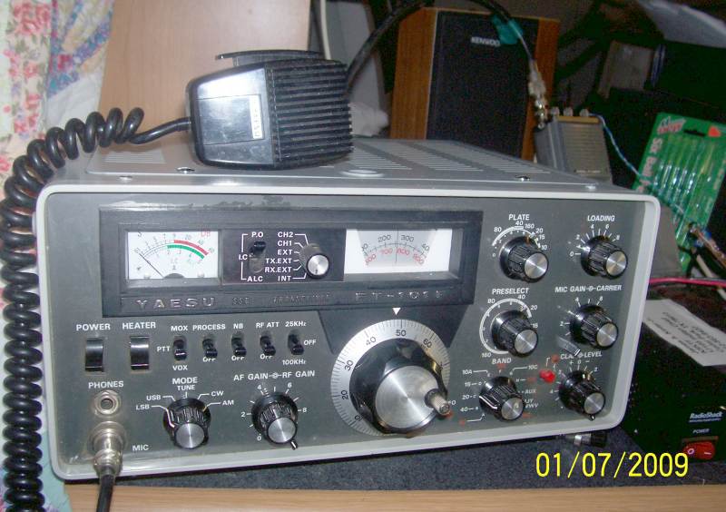
SWEET RADIO!! Kyle KE5WHB and I then made up a 20Meter 1/2wave dipole out of 2 pieces of 12awg copper wire and a PL connector,
strung it between the house and the workshop, and I gave it a test. 1st DX contact on 20M was a gent name Mike K0BUD in Minneapolis MN :-O
(1st contact of any sort on HF was John KE5RS up in Leander....)
So I played with it most of the day with KE5WHB in and out of the room, and the rest of the family out shopping/etc.
I eventually heard a gent looking for all counties, all lighthouses and all islands. Pile up everytime he finished with one person.
Try as I might, sounded like Rick AA1KS on Moose Island Maine wouldnt be able to catch me,
but I would still try (sometimes adding "Austin TX" on the end of my call).
The the last time I tried, I heard him ask for the Austin TX station, and I was in !!
WOW !!! Moose Island Maine (the last island up the east coast before you enter Cannuk territory) on this nice fine radio
and a homemade copper-wire dipole up all of about 10-12 feet!!
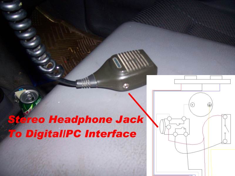
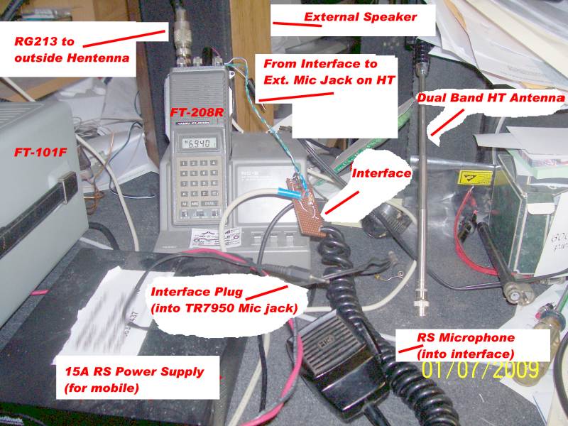
Brian AB5KT wanted to see how I have my interfacing setup here at the station, and what the TR-7950 Mic looked like after
I modified it with a jack to accept the interface to the PC.
Here is what the mic looks like:(click to enlarge)
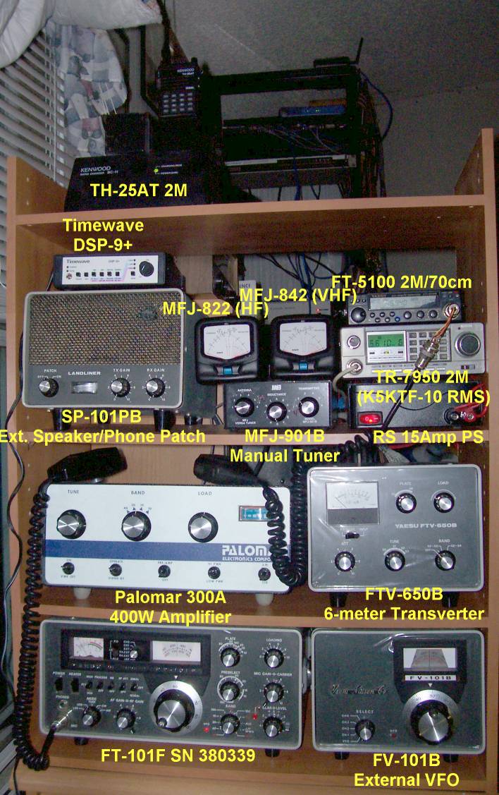
And here is what the station looks like (excuse the mess, have been very busy lately, and I REALLY need to simplify all this.....)
UPDATE 1-18-09:
Here is more stuff to clutter the web page.....
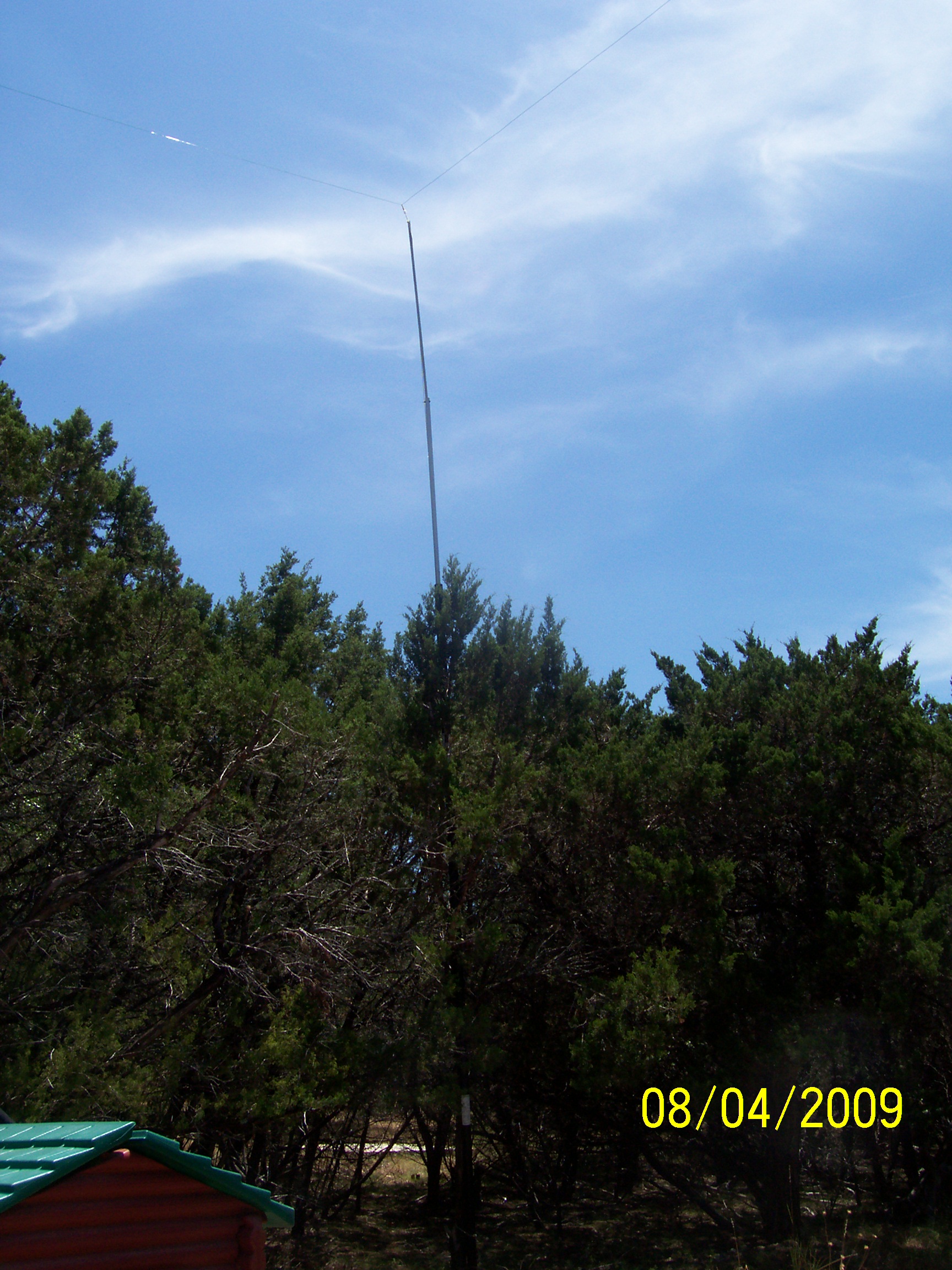
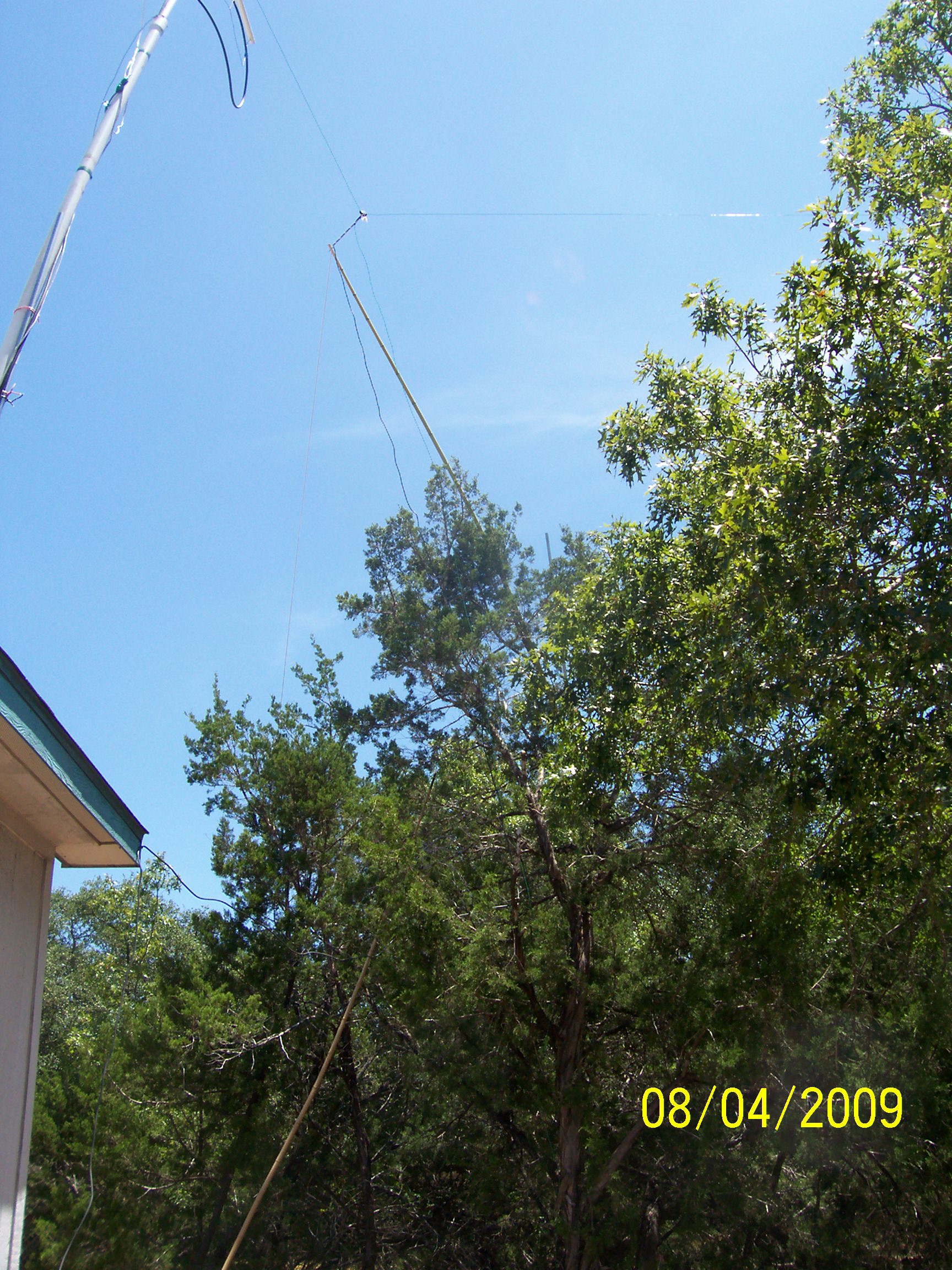
Just redid the 20Meter dipole.:
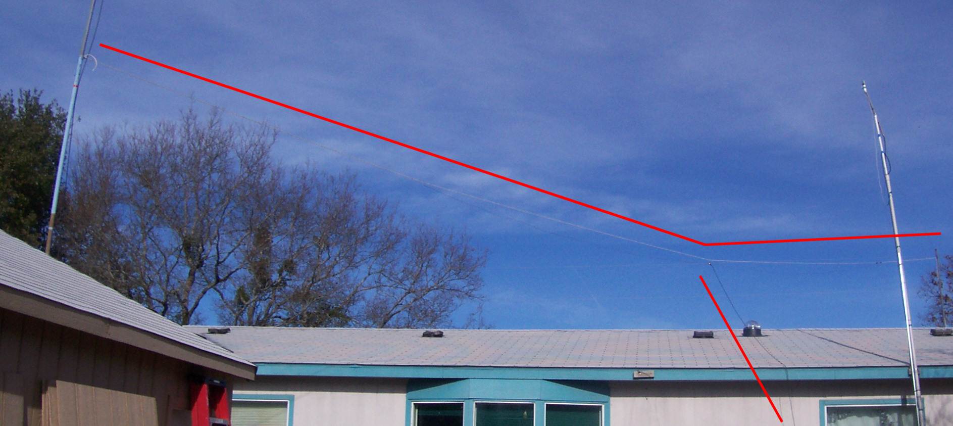
Under the red line I drew in the picture is the new rope from the mast to KE5WHB's old antenna mast,
then the dipole hangs under the rope, so we dont have the horizontal tension on the actual wires anymore.
The vertical red line parallels the coax coming down.
The dipole 'faces' almost perfect due north. Surprisingly I hit Kingsman AZ after getting the antenna back up today.
I wouldnt expect it off the end of the dipole.
ALERT ALERT --- 1ST INTERNATIONAL CONTACT ---ALERT ALERT
I just hit PY2EL in SAO PAULO BRAZIL off this antenna and the FT-101F !!!
UPDATE 10-3-09:
Today was Belton TX Swapfest !
Picked up the SP-101PB Phone patch/External speaker module for the FT-101.
There was a guy who had the FL-2100B 800W amp for the 101 "station", but unfortunately,
I didnt have enough to make a significant offer.:-(
2 weeks ago, I got with a gent near San Antone who has both the FV-101B external VFO
and a FTV-650 6-Meter transverter, so Im hoping they will arrive sometime this week!
Another gent today had the YD-844 desk mic, but he was asking a bit more than I though it was worth, so I passed.
Im sure another will pop up somewhere.
Looks like Im on my way to building a full FT-101 station!(as pictured HERE)
I think the hardest parts to find will be the QTR-24 world clock and the YO-100/101 scope that goes with the full system.
If anyone knows of whereabouts of the items I am missing, feel free to email me with asking prices or contact info.
My email address is good on QRZ.com.
UPDATE 10-6-09:
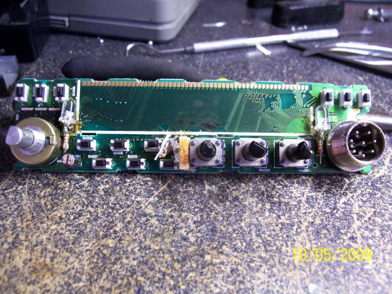
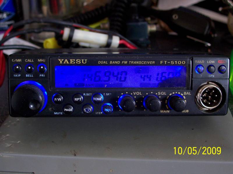
I had bought the FT-5100 from a friend, John KE5RS, which initially had QRP on the 2M side,
the black LCD leakage, and the backlights (grain bulbs) were burnt out.
The QRP problem was caused by the Beryllium Oxide substrate in the PA module.
It is very efficient at removing heat, but expands and contracts faster than the trace/solder,
so there was a small split in the one trace. Heat up the board, and solder the trace back together.
BINGO!! 50 WATTS AGAIN!
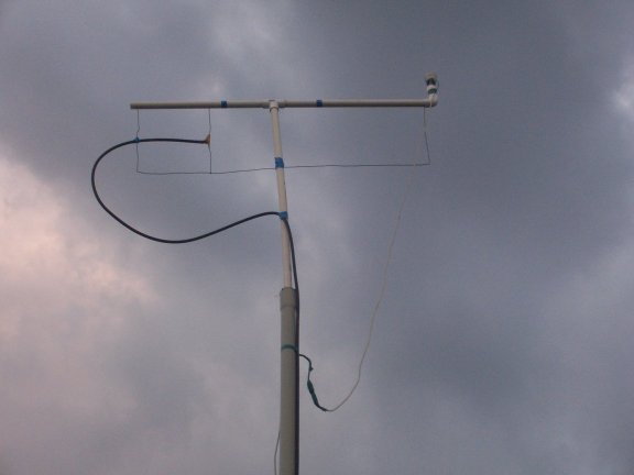
As a side note, I tried just for fun hooking the 5100 up to the 2M Hentenna (shown at top of this page).
Of course, it worked fine on the 2M side of the radio. BUT WHAT WOULD THE 440 DO???
SWR was a shade high (about 1.8/1.9... I like 'em low personally for Solid State Stuff), but it IS working just fine on it!
So then there was the missing backlight issue. Its readable when there is ambient light, but invisible with not enough.
Well, if Im going to go through all the trouble of replacing the bulbs, LETS PIMP IT OUT!! :-)
220ohm, 1/4W resistors and 3.7vdc20ma 2600mcd blue LEDs (276-316 at Rat Shack)
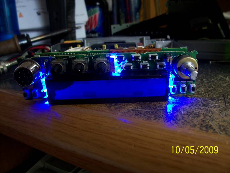
The original bulbs (manual says) were 60mA each (180). These LED's draw 20mA each (60).
That means its drawing about 60mA more than when I got it, but 120mA less than what was OEM.
Oh, and the 6M transverter and External VFO for the FT-101F arrived today :-)
I know what Ill be playing with tonight ! lol
UPDATE 10-8-09:
I got it all hooked up (except no 6M antenna yet).
Here is what the shack looks like right now:
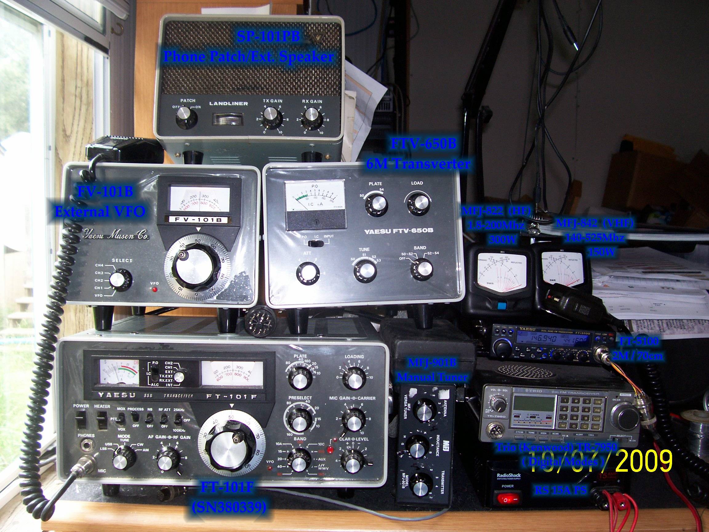
(for a good close-up, click on it)
Now my next project will be to build a shelving unit for all this.
While Im at it, here is the latest Antenna layout.
The 4 corners shown support the 80M loop, fed from a 42' piece of 75ohm RG6 for a transmatch.
 |
 |
|
 |
||
 |
 |
If you get the same make and model hoops, the poles will interlock top into bottom, and you can stack them.
Some have larger diameter poles, so you can drill holes about a foot from the top of the larger one and about 6 inches from the bottom of the smaller one,
and throw a large bolt through to keep it from sliding too far inside the larger one.
Then on the other 2 corners, I used some bamboo shoots from my neighbor's yard, where he has a ton of it growing.
On everything, a U-bolt or an eye-bolt at the top, then run rope through that and tie it in a loop to the antenna wire.
Once the support (pipe/bamboo) is up and lashed to a tree, pull down on the rope and tie it off to raise the antenna.
SIMPLE! (and CHEAP!)
UPDATE 11-22-09:
The Hentenna is DOWN! And the webcam with it.
I am leaving the Java box at the top there for now, so when I do get the cam back up, the code will still be there.
I took the Hentenna down so I can use the mount and the coax for the new 6-meter dipole I made last weekend.
So I am now monitoring 50.125 USB most of the time when Im at my desk. I have made 2 contacts on it so far, KE5RS of course,
where him and I tested the FTV-650B 6M transverter and then we tested/worked split with my new FV-101B external VFO,
ME=50.165 RX/KE5RS=50.180 RX.
Then this week I had it on, and heard Tom K5VH down in Dripping Springs. I reached out the window and armstrong-rotor'd the mast,
and he came in a solid S9+. Afterwards, I noticed how very directional that dipole is, so I spun it around a bit, finding the low and high of my QRM,
so now I know in one of 2 directions where to start doing some RDF for the neighborhood noise.
OH! and last weekend (15 Nov 2009), the family and I traveled over to Thorndale TX to visit with AB5KT and his mini-field day/BBQ he hosted.
He set up a 160M loop about 20 feet in his 'backyard', and had his TS-2000 running.
I sat down, got the rig on 20 meters, and hit KP2T in St Thomas, Virgin Islands
(Im not impressed, as thats just a tad past the FL Keys..... :-) ).
So, wanting to do something a bit more spectacular, I scanned around, and proceeded to log.....
JH4UYB, JA4DPL, JF9KTS!
My very first Japan contacts! (And I think the first J's for his radio as well...). Woo hooo!
And the food was just as good, if not better! Kudo's to Sue and Brian for a nice spread and an awesome day!
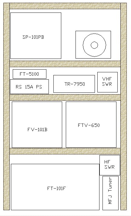
UPDATE 3-9-2010:
Finally broke down and bought a $20 shelf unit for the shack.
And since I had to tear down the whole mess, I decided to hook up the nice little Palomar 400W amp that I received from Dan N5VLF some time ago.
I had put it off, since I do run an 80M loop, and my MFJ tuner is rated at 200W max, so I didnt want to start my own temporary light show! :-)
But I went ahead and made up a jumper and hooked it up.
Now, you may ask.. This guy just hooked up a 400W amp after running barefoot (100-120W) so far in his Ham career,
do you think he would actually NOT turn it on and try it out??? :-)
Yes, I admit, I did... :-O
But I made sure to keep the carrier (when tuning) and mic gain down at first
and S L O W L Y bring it up, until it was just under 200W on the crossing-needle meter.
Just too bad 20M closed about 4 or 5 hours ago, so no one heard my ID (or came back to me if they did).
But here I sit, right now, with all antennas tied into the coax switch, grounding each and every one of them,
because of a 2nd squall line coming through tonight.
So now I have to go to bed, knowing this thing is working (a couple peaks hit about 210W without any crackling noises)
and not being able to play on it right now (12:30am CST).
But tomorrow should be fun ! *wringing hands in anticipation*
Night y'all !
UPDATE 3-27-2010:
A couple days ago, a neighbor, we will call him "Sam", and I met for the first time. We discussed many things, and then he mentioned he had
an old radio him and his wife would communicate with when they lived in Colorado, since other comm was scarce on the west slope at the time.
Turns out, its a Ranger FCI-2970 all-mode mobile, (100W SSB, 50WAM/FM/CW)
that someone had done mods to give it Chicken Band access (since he was unlicensed).
I gladly accepted the gift, as well as a 102" whip he no longer needed.
The next day, I opened the rig on the bench, undid the CB mod,
unsoldered the dead battery and replaced it with a battery clip off a PC motherboard and new battery,
And fixed some sloppy wiring/soldering that had been done (looked like previous accidentally clipped wires).
One annoying mod that I havent figured out how to undo is that the
roger-beep is ALWAYS on, and punching the "r.beep" button takes the rig to CB Ch. 9.
Yesterday, I installed the whip on a blank 2" receiver hitch tube, and mounted the radio in the truck.
Last night, I called up KE5RS on Sparky (his 441.6 rptr), and we went over to 28.420 to try it out.
W2MN also came along for the ride, and they garnered good reports from the rig (including CB jokes about the roger-beep....).
Then I drove over to Sams to show him its operation.
On the drive down the street, I was hearing Santiago Chile and Honduras coming through on contest.
I tried to work it, but it was pile-up hell.
Sam seemed happy it was getting used, we discussed some neighborhood news (a.k.a. gossip) and I bid him farewell.
As I pulled into my driveway, I scanned 28.300-500 to see what else I could hear.
I heard a PW5G calling QRZed, so I tried 3 times. On the 3rd try, he called my call,
we gave signal reports and QTH, and he was off QRZeding again.
I didnt know offhand the PW prefix, so I immediately came in to log it in HRD,
and when I pulled up QRZ.com, the gent was south of Sao Paulo BRAZIL!! 5100+ Miles !!
I think that gave me the confirmation this rig is working :-)
KE5RS and I did more testing this morning on it, checking out all the modes (except CW).
On FM., he sounded like we were on 2M FM, and he gave me hints to tweak my TX.
He stated, that for the price, it was an excellent radio.
I told him, "Well, it would be hard to get my money back :-) "
THANKS SAM!!
Oh, and I had installed an HSMM-MESH node a few weks ago
Well, thats all for now. Maybe next time you visit, I will have cleaned this webpage up, since its getting to look like my office :-)
(Actually, Ive cleaned the office, so I REALLY need to get a CRM installed and running here!lol)
More to come as I have more time.
If you would like to email me, its just Jim AT the domain name that got you here (without the WWW.)
Or look me up on QRZ.com. The info there is all correct.
73's!